|
ĪĪ
RYQ-5 Soft-bearing balancing machine
 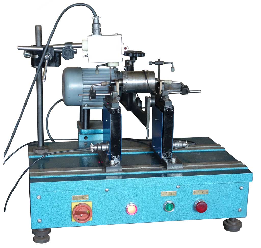
The machine is not a simple replica of the old-fashioned soft-bearing balancing
machine, from the mechanical structure and electrical measurement system has
been completely redesigned. Mechanical durability greatly improved.
1. Support frame: soft support frame structure is simple, stable performance.
The use of speed sensor, no lateral sensitivity, lower limit requirements,
making the operation requirements simple and quick. Compact structure, strong
and reliable, the mechanical model is reasonable, the rotor of the actual
imbalance can be supported by the frame and sensors to truly reflect. And this
is to ensure the balancing machine measurement accuracy of the most basic part.
Balance can be visually hand to feel the state.
Small rotor balance is too much trouble, the soft bearing mode is the mode of
operation closest to the state, can almost run the speed measurement. Therefore,
it is preferable that the high-precision balancing is performed with the soft
supporting operation.
This years of soft bearing balancing machine market has the amount of
regression is due to the high rate of structural failure caused by the machine,
and now we design an ultra-low failure rate of the rack.
Using BL-16 general computer electrical measuring box as a supporting
measurement system,
The system has the functions of automatic sensitivity control, automatic (or
manual) storage of rotor data, direct readout of measured data (unbalance
magnitude and angle), keyboard input of rotor data, balancing of dynamic and
static-even balance.
The rotor data can be saved and extracted by the keyboard. Up to 99 rotor data
can be saved.
The machine is designed for horizontal soft support, computer measurement
digital table display and other common forms.
In this case,
2. The basic parameters and the main technical performance indicators
2.1 Basic parameters
2.1.1 workpiece quality range of 0.2 ~ 5 kg
2.1.2 Accidental overload of each support 3.5 kg
2.1.3 The maximum workpiece diameter of 310 m m
2.1.4 workpiece journal range of 5 ~ 30 m m
2.1.5 The maximum sensitivity of 0.005 g
2.1.6 The maximum distance between the centers of two supports is 400 mm
2.1.7 The minimum distance between centers of the two supports is 55 mm
2.1.8 Motor power 90 W
2.1.9 diameter belt drive diameter range of 8 ~ 90 mm
2.1.10 workpiece speed 1000 ~ 6000 r / min
2.2 The main technical performance indicators
2.2.1 The minimum achievable residual imbalance emar Ī▄ 0.3 g.mm / kg
2.2.2 Unbalance reduction rate URR Ī▌ 90%
ĪĪ
ĪĪ
ĪĪ
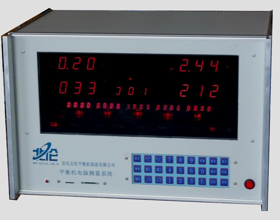
BL-16 Electrical universal measuring
instrument for balancing machine
This is a special computer on the
balancing machine, you can handle the balance of the various conditions of the
signal. Can be calibrated to single-sided and double-sided measurement mode.
The core circuit of the electrical measuring box is 32-bit industrial
single-chip AC direct high-speed full-wave sampling, software sine wave
correlation function filtering, has a good filtering and frequency tracking
performance. As a wide range of tracking, electrical measuring box with only a
block speed range of work to facilitate the user. Especially the use of
automatic bandwidth switching circuit, a reasonable solution to the electrical
box response to the rapidity and stability of the contradiction between the
electrical measuring box with excellent low-speed performance. The speed of the
electrical box instructions 80-6500RPM.
The electric box can automatically set the measured speed memory
measurement data. Once again, the power box automatically enters the next
measurement.
Record button. If the user needs to record the test results in writing, press
the Record button to record the measurement data to the SD card (or tf card) for
permanent recording or printing of the test report.
This machine uses the whole vector solution, through the sensor measurement of
the K coefficient group, the vector to calculate the above C influence
coefficient group.
The accuracy of resolving precision has important relation with the position of
the measuring point of the two groups of sensors. The position of the signal
taken corresponds to the maximum point of measurement difference of the weighted
surface (resolving plane) of the rotor. (Ie the mechanical structure determines
the measured signal separation).
Phase calculation range of 360 degrees,
As a result of the full vector operation, the separation of the calculation is
not limited in value, in other words in the balancing machine on the left and
right sensor line interpolation can also make the normal separation calculation.
The result of the calibration is determined by the calibration method. The
result of the weighted calibration shows the amount of excess, and the balance
of the process is removed by removing the unbalance.
Electric measuring box can be measured at any time after the completion of
changes to 180-degree process of increasing the balance.
ĪĪ
MATHEMATICAL CALCULATION OF CALIBRATION
PROCESS
A test re-input M1 input M1 value and angle, measured value V1 (left VL1,
right VR1)
(M2) (left side VL2, right side VR2) M2 value and angle, measured value V2
(left side VL2, right side VR2)
Calibration quality factor dp1 = | V1 / VL0% | Percentage of the scaled
quantity to the initial quantity
Dp2 = | V2 / VR0% | When less than 30% that the lack of calibration.
Vector calculation formula
UL=C11*VL+C12*VR
UR=C21*VL+C22*VR
The storage parameters for each rotor
are 11 values:
C11 ĪŽ11 C12 ĪŽ12 dp1 dp2 C21
ĪŽ21 C22 ĪŽ22 n
Exit the calibration state,
calibration complete exit calibration status.
In this case,Instrument display results: (vector calculation results)
UL0ĪŽUL0=C11ĪŽ11*VL0ĪŽL0+C12ĪŽ12*VR0ĪŽR0
UR0ĪŽUR0=C21ĪŽ21*VL0ĪŽL0+C22ĪŽ22*VR0ĪŽR0
ĪĪ
Address: Wanfeng
rd.Dongmenwai Str. Xuanhua Hebei Province China
Post code:075100
Tel: +86 313
3175800
ĪĪ
ĪĪ
|
ĪĪ | |